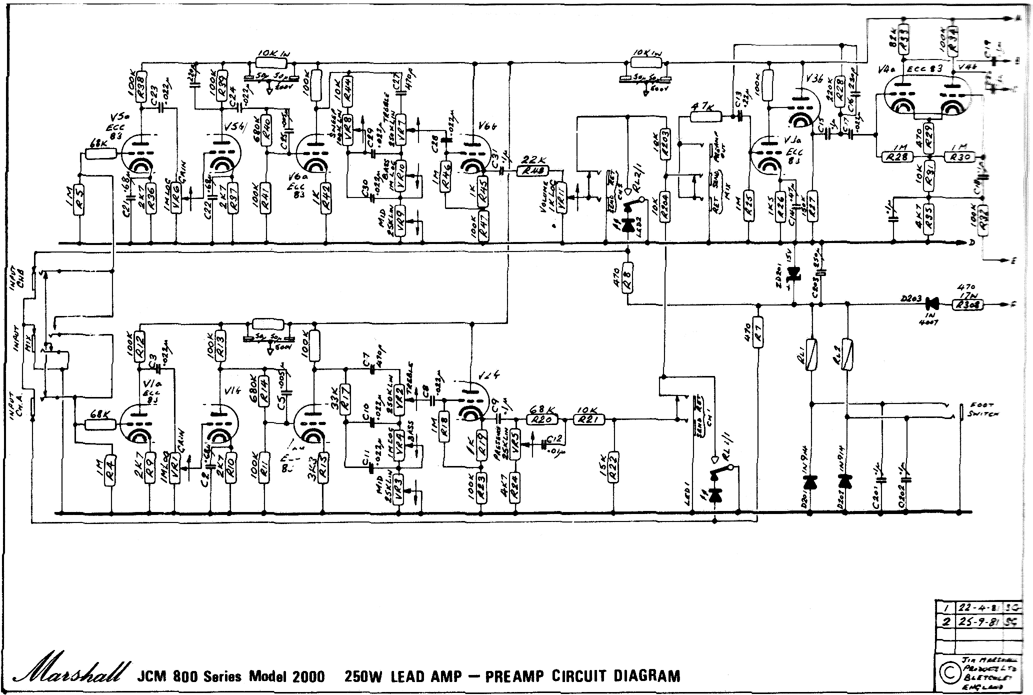

- #MARSHALL JCM 2000 DSL 50 SCHEMATIC DRAWINGS HOW TO#
- #MARSHALL JCM 2000 DSL 50 SCHEMATIC DRAWINGS MANUAL#
Many different models share the same output PCB. Now what is the physics /chemistry of all this? I assume something hygroscopic is grabbing moisture then forming a conductive salt that stays within the micropores of the surface of the glass fibres, but why temperature increasing the conductivity, what salt has highly temp dependent conductivity, we're only talking 50 degree C or so. I will explore this, as hard wiring the HTs to isolated valve bases,only, is quite different to hard-wiring all HT traces. The cathode lines have 2/3 orders of magnitude lower resistance to ground so any such effect not so obvious there These are the small bottles not the hotter big bottles, something to do with that metal shield plate for them? I'm assuming the effect is at the valve base through board, hot pins rather than where the anode dropper leads pass through the pcb, and passing through rather than along the surface. 1 and 2 mixes, a 50 blow Marshall (AASHTO T245) and for Level 3 mix a 75 blow Marshall. DSL means the State of Oregon, Division of State Lands. Bicycle means a vehicle as defined in ORS 801.150.
#MARSHALL JCM 2000 DSL 50 SCHEMATIC DRAWINGS MANUAL#
ODOT Bridge Design Manual and accompanying Standard Drawings.

It would be nice to find a schematic for this specific variant, but only. (just tested car again key stopped locking and unlocking doors) I knew i'd seen this problem before from someone else.i finally found the thread from 2010.lol.:thumbup: Another guy had the exact same problem as you and it turned out to be an 'oxidized ECU Connector'.he used some Carb cleaner to clean it and it worked.
#MARSHALL JCM 2000 DSL 50 SCHEMATIC DRAWINGS HOW TO#
How to program bmw key fob e90post trunk lid. I think it maybe the 2 x ECU's are located on the passengers side under the particle filter in black plastic box but 'm50b25' should be able to direct you. Megger showed nothing untoward With no V1 in place, the grid socket pins measure about 10 or 20mV DC, wave hot air over the valve base and the readings shoot up to 100 to 200mV, just like applying a magic wand. No E number of board supplier found but I would say, by trying to press a needle into the board, it is epoxy rather than polyester composite. Locally heating with hot air (low setting) for 20 seconds the voltages shot up 5 or so mV but soon dropped back to where they were, unlike the problem around V1 it would seem. Main bias results monitoring every 5 minutes for the first 15 minutes rate of increase is falling passing 10 to 15 minutes in one side rising 1.0mV per 5 minutes and the other side 1.5mV per 5 minutes starting from that 15 min reading of 76.9mV and 68.2mV should be about 90mV over an hour. But the first thing I will do is check for o/p bias drift, then heating the pcb with hot air and a 2Gohm megger and then remove V1 and see if hum returns then replace and monitor DCs around V1 on heating, No mention of that Marshall Forum page about hum but it could be these pcb problems around V1 the immediate problem.


The Russian markings are quite visible and there is no sign of overheating of the bases, still light brown, and the pcb around looks as new. They look brand new except for simple dragon's teeth marks, ie not repeatedly moved around. The valve set that are in here are all 2009, he took out the new ones and replaced these used ones. Only just got around to building a Dexion support frame so I can toss these sorts of amps around with gay abandon, and not risk the bottles. I should be able to get back to it in a couple of hours. BTW: Marshall are a total bunch of arseholes. If no new PCB is available from Marshall at a reasonable price - just add a bloody fan!!!!!!!!!!!!!!!!! A single 120mm, 240VAC fan blowing directly on the OP tubes from below cures the overheating / bias runaway problem completely. It is made from UTTER CRAP!! However - uber clever fixes involving a Dremel or mounting resistors in mid air or any similar hare brained ideas are all just re-arranging the deck chairs on the SS Titanic. ** The PCB material is definitely the cause of the problem. Once force warmed and hum level risen it is reluctant to go down again from natural cooling or from freezer spray - what process is going on with in it? Now to replace by fudge fitting to in situ component leads or take the whole thing apart to replace properly? Marshall saw fit to bodge 3 resistors by cutting off the originals and flying replacement ones to the cut wires - so whats good for the goose. C13 100V 1uF at V1(A) cathode, of all things, is highly sensitive to hot air.


 0 kommentar(er)
